Dropper Cable After-Installation Testing: What to Specify Before Energisation
A passed factory test tells you the assembly was sound when it left the plant. It says nothing about what happened during the pull-in, the hang-off, the bend through the tower base and the final connector seating. After-installation testing is the check on that second half of the journey, and on many projects it is specified in a single vague line.
Why a Second Test Is Not Redundant
Our FAT checklist covers what a factory report should contain. Pre-termination also removes offshore field jointing, as discussed in field joint versus pre-terminated dropper cables. Neither removes the handling risk: the assembly is still pulled, bent, clamped and plugged in on site. Damage that occurs there is invisible to any factory certificate.
Testing is typically carried out after cable installation, after repairs, before energisation, or as part of condition assessments of existing assets. Treat the post-installation test as the acceptance gate for the whole delivered system, not a formality.
The Standard Reference Point
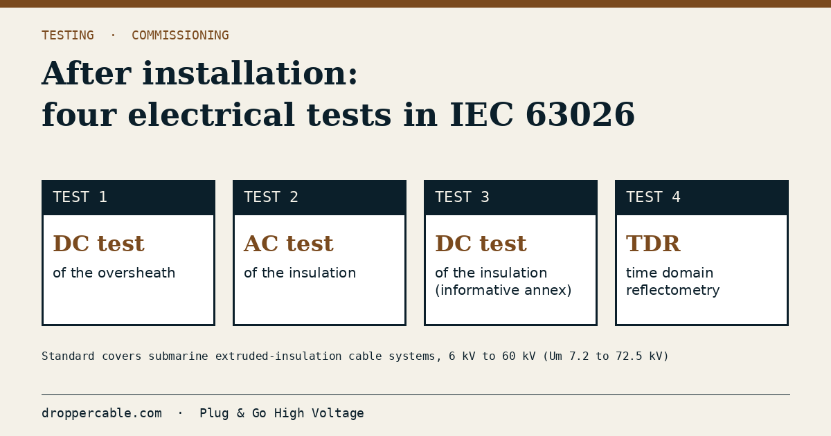
IEC 63026 covers test methods and requirements for submarine power cable systems with extruded insulation and their accessories, from 6 kV (Um = 7.2 kV) to 60 kV (Um = 72.5 kV). It was written with offshore wind inter-array cables in mind. Its after-installation clause lists four electrical tests: a DC voltage test of the oversheath, an AC voltage test of the insulation, a DC voltage test of the insulation (given as informative guidance in an annex), and time domain reflectometry (TDR).
Two cautions apply. The standard excludes accessories with only a mechanical function, such as hang-offs and armour clamps, and special cables such as dynamic cables. A dropper assembly sits partly outside that neat scope, so the project specification must say which test regime governs the dropper section and who owns the result.
Methods You Will See in a Test Plan
Test providers commonly list AC resonance, VLF, partial discharge measurement, damped AC (DAC), TDR fault location, insulation resistance and tan delta. They are not interchangeable.
- AC resonance applies power-frequency voltage and is closest to service conditions.
- VLF uses a much lower frequency and a lighter, more portable set; IEEE 400.2 is the guide for VLF field testing of shielded power cable systems.
- PD measurement looks for discharge activity that a simple withstand pass would miss.
- TDR records the cable’s reflection signature, useful as a baseline and for locating damage after a fault.
No method is right in the abstract. The right one depends on the voltage class, the accessory design, the equipment that can physically reach the turbine, and what the supplier’s design was qualified against.
What the Contract Should Say
Vague wording such as “cable to be tested after installation” invites disputes. Specify:
- The test method and the standard it follows, cited by number.
- The test voltage as a multiple of the rated phase-to-earth voltage, plus its duration, written into the spec rather than left to the contractor.
- PD sensitivity achieved and reported, not only “no discharge observed”.
- A TDR baseline captured at handover, so future fault location has a reference.
- Who witnesses the test, and who may sign it off.
- The acceptance criterion and the remedial route if the assembly fails. Replacement logic matters here, and it connects directly to maintenance planning for dropper cables.
Practical Takeaway
Treat the factory test and the site test as two halves of one evidence chain. If the FAT report quotes a voltage and a PD value, the site test should be able to reproduce the same kind of measurement, so the two can be compared directly. If it cannot, you have lost your best diagnostic.
Check also that the test kit can physically be on site. Reynard lists post-installation, pre-energisation and post-repair testing among its services, and an offshore mobile testing unit for resonance testing and commissioning of cable systems up to 66 kV, designed for vessel and platform use; whichever provider you choose, confirm equipment capability and mobilisation before the vessel is booked.
Sources: IEC 63026:2019 — Submarine power cables with extruded insulation and their accessories, 6 kV to 60 kV, IEEE 400.2 — Guide for Field Testing of Shielded Power Cable Systems Using VLF.