Dropper Cable Bend Radius: Reading the Spec Before You Plan the Route
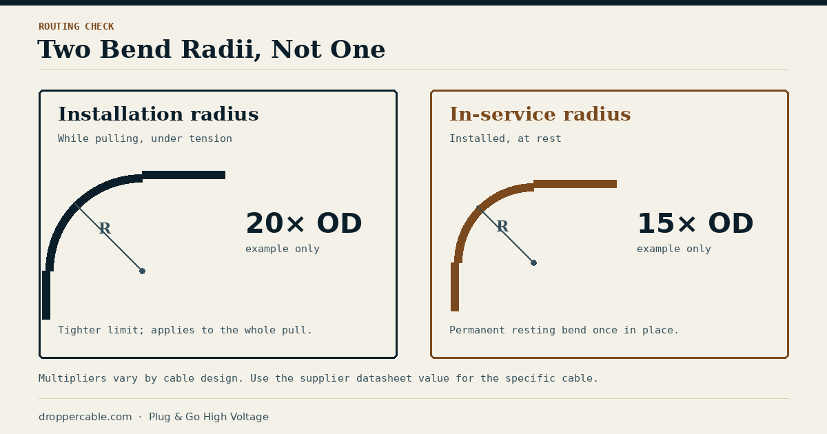
Ask for a dropper cable’s minimum bend radius and you’ll usually get a single multiplier: some number of times the cable’s outer diameter. It’s a useful shorthand, but it hides a distinction that causes real routing problems. There isn’t one bend radius, there are at least two, and they apply at different moments in the cable’s life.
Two Numbers, Two Situations
The first is the radius the cable can tolerate while it’s being pulled or handled, under tension and with the cable still moving. The second is the radius it can sit at permanently once installed, with no tension and no movement. The installation limit is the tighter constraint on the cable’s mechanics and is normally the larger number, because a cable under load is more easily damaged than one at rest. One manufacturer datasheet for a high-voltage XLPE cable, for example, gives 20 times the outside diameter during installation and 15 times once in place. That’s a general-purpose cable, not an offshore dropper, so treat it as an illustration of the pattern rather than a number to design to.
Published multipliers also vary by construction and standard. Rules of thumb in the range of 12 to 20 times the outer diameter circulate for shielded single-core cables, and the right figure depends on conductor type, screen and sheath design. The only value that matters for a given project is the one on the supplier’s datasheet for that specific cable, and the installation specification that governs how it is pulled.
Why It Bites in a Turbine Tower
Dropper cables are routed in tight places. They leave a transition piece or tower base, run through a limited volume, and end at switchgear or a transformer with a fixed bushing position. A stiff, heavy single-core cable with a large outer diameter can need a radius measured in metres, and the geometry of a tower base doesn’t always leave that room. Planning on a drawing at the in-service radius, then finding during installation that the pulling radius is tighter than the route allows, is a common way for a route to pass review and fail on the day.
Three details compound it. The radius is measured on the inside of the bend, and the cable’s real clearance is its outer diameter plus any cleats or protection. Preassembled lengths have a connector and often a stiffer transition at each end, and the stiff zone near a termination usually can’t be bent at all. And the bend has to be held through the whole pull, not only at the final resting position.
Questions Worth Asking the Supplier
A short list is enough to expose most gaps:
- The installation radius and the in-service radius, stated separately, with the cable diameter they are multiples of.
- How long the rigid zone is at each connector end, and whether bending is allowed inside it.
- Whether the figure assumes a given pulling tension, temperature range or cable-pulling aid.
- Whether the assembly’s factory acceptance test covers the as-built length and routing, so the cable that was tested is the one that will be installed.
Fitting the Cable to the Route, Not the Other Way Round
The cheapest time to fix a bend-radius problem is before the cable is made. A preassembled system built to the actual tower geometry, with the length and exit angles set from a survey instead of a catalogue default, removes most of the room for site improvisation. That is the argument behind factory-terminated assemblies generally, and it’s why Reynard fits the length and connector orientation to each project’s routing before assembly and testing, instead of leaving the final geometry to be worked out inside the tower.
Sources: 500 kV XLPE cable datasheet (installation vs. in-service bending radius), WESCO — what is the minimum bend radius of cables.